

The Curious Case of Jehu's Sleeping Scooter Batteries - How To Wake Them Up
It's a tale full of hope, lessons, struggles, and breakthroughs!
Jehu struggled at first, but with his signature spunk and get-it-done attitude, he found the way to awaken these beauties, and to victory!
Jehu has made videos about how to do it. Here's a step-by-step guide to awakening the scooter batteries BMS with a digital key.
First you will need to get the JAG35 scooter battery packs: 40 CELL NCR18650BD 18650 LITHIUM SCOOTER BATTERY PACK W/CASE


These scooter packs normally come with female connectors attached, so you will need to get the male connectors: MALE BATTERY CONNECTOR FOR SCOOTER BATTERIES OKAI ES200G

These are the male battery connectors you need for your OKAI ES200G scooter battery modules to connect to the programmed Arduino that "wake up" the scooter batteries. Each battery pack needs a male connector.
Any voltage below 30v at the Discharge port is an indication that the BMS is hibernation mode. The Internal BMS can be turned on by applying voltage to the charging port (smaller cable) The battery pack will remain in the "ON" state for as long as it has a voltage of 30v or above and without a load. Applying a load will cause the battery to shut 'OFF" after 5 seconds then remain off for 60 seconds, ON for 5 seconds, OFF for 60 seconds for an indefinite amount of cycles. Using this Arduino Controller connected to the blue cable will instruct the BMS to remain ON for an indefinite amount of time.
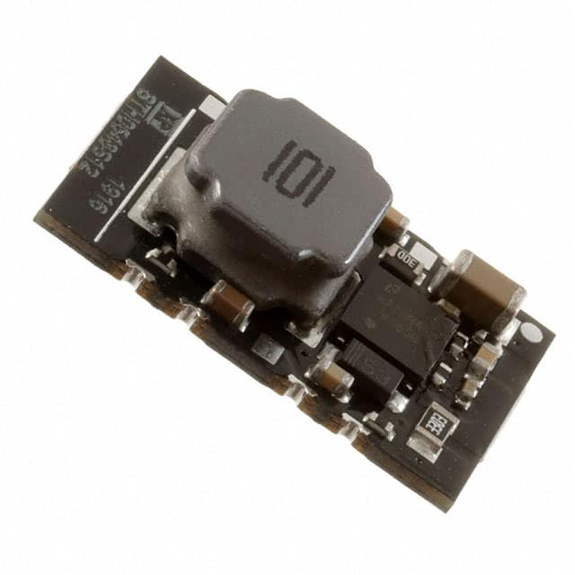
You'll need this Arduino Controller: PRE-PROGRAMED ARDUINO TO WAKE OKAI ES200G SCOOTER BATTERIES

This MicroController is used in conjunction with the Okai ES200G scooter Battery Packs. These battery packs require a status/unlock signal to their BLUE (Tx) wire with 9600 Baud serial: 0x3A, 0x13, 0x01, 0x16, 0x79
Then the battery replies with an extensive status report on the GREEN (Rx) wire. We are currently designing a device to display the status report from the battery, but for now we can turn them on and use them to power many 36v devices. The Arduino is pre-Programmed with the following code:
void setup() {
Serial.begin(9600);
}
void loop() {
// 0x3A, 0x13, 0x01, 0x16, 0x79
Serial.write(0x3A);
Serial.write(0x13);
Serial.write(0x01);
Serial.write(0x16);
Serial.write(0x79);
delay(5000);
}
You'll need 1 Arduino per scooter battery pack to keep it awake, or an ACTIVATING DONGLE to activate x1, x2 or x4 scooter packs. For more than 4 scooter packs, you can DIY a solution to send the signal to multiple packs at once, like Jehu's prototype here: DIY Powerwall Design - PCB PowerStrip.

(Shhh, just between us, Jehu has been working on a DIY Powerwall version of the dongle. It isn't ready for production yet, but it will be soon. Stay updated by signing up for Jehu's early access updates to be among the first to know about new products and deals: https://mailchi.mp/50c08f16b8db/newsletter-landing-page )
To power your Arduino you have to use a DC-DC that makes the battery packs 42v down to at least 3.6V. Jehu recommends the JAG35 ACTIVATING DONGLE which includes a DC-DC, or you can buy it on it's own: DIGI-KEY STH0548S3V3.
Here's a simple diagram for reference.

Most of these battery packs are in hibernation mode, this means that even though the pack is resting at around 30v the output connector shows sometimes 1v to 15v. This means the MOSFETS in the BMS are off.
To use the battery you have to charge the battery pack to 42v. Once charged, some packs will automatically turn on, others will require you to bridge the negative pins on both connectors together using a jumper cable. Applying 42v to the small charging port will also take the battery out of hibernation. If you don’t have the small connector you will have to cut the original connector and solder in your own. XT60 connectors work great here.

Jehu explains more in this video: Okai ES200G Battery Arduino Controller - DiY Powerwall Building
For more details, check out these videos where Jehu explains more on how to wake up the batteries:
The Best $125/Kwh DIY Powerwall On the Planet
How To make a 72V eBike battery capable of 1800W continuous
This should get you well on your way to "waking up" the scooter battery packs for your DIY power build.
Please share your comments with below, and remember to check out the deals in my store. Keep on building!
- Jehu
Visit my store:
![]()
7 comments
I purchased this battery and I need to wake up the bms. I’m not sure of how to do it. I read the instructions but I’m still unsure. (750Wh eBike Battery! Our EB4 36v 21Ah eBike Battery has a 750Wh capacity, containing x80 18650 lithium-ion cells).
Hi Jag35 fans,
I have owned 4 of these scooter packs and a 4x dongle for about a year now, all has been working great, but I left the battery packs alone for about 4 weeks and I can no longer use any of the recommendations described at https://jag35.com/blogs/jehu-garcia-battery-university/the-curious-case-of-jehus-sleeping-scooter-batteries-how-to-wake-them-up to wake up the batteries.
I swapped out the small charging port to a XT60 to wake up/charge through this connector, but no success. There is also no light on the 4x dongle when I try and charge that way either.
Does anyone have any ideas what might have happened? Again, the batteries haven’t been touched for about 4 weeks, but I assumed I would always be able to bring them out of any hibernation.
With thanks,
Paul
bought two of these es200 batteries and looking if anyone has any of the Arduino or whatever they are called to wake them up and keep them on as I would like to us them for my ebike projects. please any help would be much appreciated.
Hello, what setup would be best to charge (6) 40 cell Panasonic packs in parallel? Thank you
A follow-up to my previous comment, not yet approved as of writing this:
I probed the green wire on the scope and I can see it was getting pulled low and trying to communicate at 9600 bps, but not getting very high. I connected my USB to TTL serial adapter, the RX pin to the green wire, and connected a 1kΩ resistor from the green wire to the +5v wire of my USB adapter to allow it to be pulled up and there it is. After every time the 5 activation bytes are sent, I get 36 bytes of data from the green wire. I just don’t know how to interpret these 36 bytes of binary data. Running a simple python program to read from the serial port and show the individual bytes, I get:
b’:’
b’\x16’
b’ ’
b’\x02’
b’\x00’
b’c’
b’c’
b’\x1c’
b’\x1c’
b’\x1b’
b’\x19’
b’=’
b’\x00’
b’\x00’
b’\x0f’
b’\x00’
b’\x00’
b’\x00’
b’\x00’
b’\x00’
b’@’
b’M’
b’\xa0’
b’\x00’
b’\x00’
b’\x00’
b’\x00’
b’\x00’
b’\x00’
b’\r’
b’\x10’
b’\x02’
b’\x10’
b’R’
b’,’
b’\xe7’
I’m hoping anyone will know how to get anything useful from this.